
1. Introduction
In the world of industrial compressed air, few machines carry the weight — literal and figurative — of the centrifugal compressor. When a petrochemical refinery needs 50,000 cubic meters of oil-free air per hour, or when an air separation unit (ASU) demands uninterrupted, pulsation-free compressed air for cryogenic distillation, the centrifugal compressor is not one option among many. It is the only viable choice.
SEIZE AIR designs and manufactures centrifugal air compressors purpose-built for these large-scale process industries: petrochemicals, steelmaking, air separation, LNG liquefaction, and fertilizer production. These are environments where reliability is measured in years of uninterrupted operation, where efficiency gains of even 2% translate to hundreds of thousands of dollars in annual energy savings, and where the cost of unplanned downtime can exceed the capital cost of the compressor itself.
This article provides a deep technical dive into centrifugal compressor technology — how these machines work, what sets them apart from other compressor types, and why the engineering decisions made at the component level determine the difference between a compressor that merely meets specifications and one that delivers decades of profitable operation.
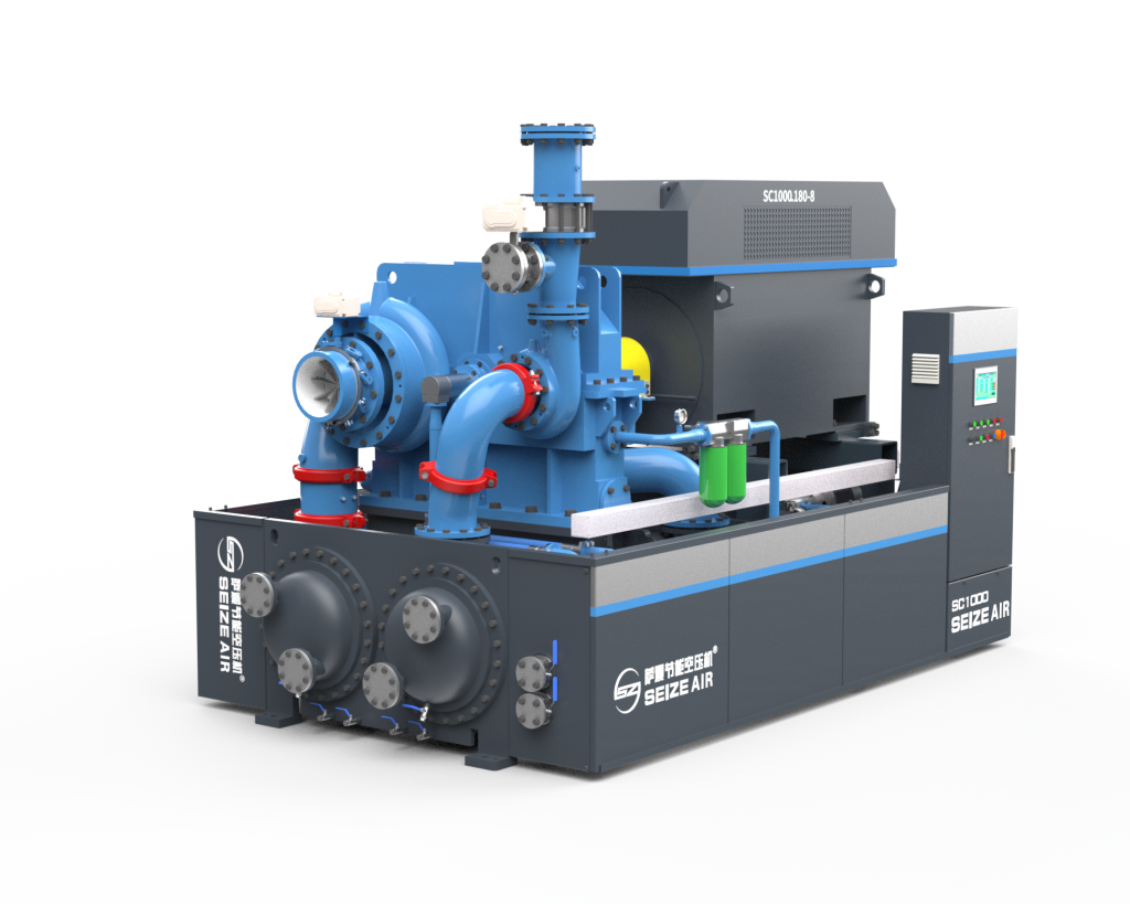
2. How a Centrifugal Compressor Works: The Physics of Dynamic Compression
At its core, a centrifugal compressor is a dynamic compressor — meaning it accelerates a gas to high velocity and then converts that kinetic energy into static pressure. This is fundamentally different from positive-displacement compressors (reciprocating, rotary screw) that trap a fixed volume of gas and mechanically reduce its volume.
The process unfolds in three stages:
Stage 1: Acceleration (Impeller)
Ambient air enters the compressor through an inlet guide vane (IGV) system, which pre-swirls the air to optimize the angle of attack on the first-stage impeller. The impeller — a precision-machined disk with curved, three-dimensional blades — rotates at speeds typically between 15,000 and 60,000 RPM, depending on the machine size. As air passes through the impeller passages, centrifugal force flings it outward, imparting kinetic energy and increasing the gas velocity to supersonic ranges at the blade tips.
Stage 2: Diffusion (Diffuser)
Upon exiting the impeller, the high-velocity air enters a stationary diffuser — a ring of carefully contoured vanes or a vaneless annular passage. The diffuser’s geometry is designed to gradually expand the flow area, causing the air to decelerate. By Bernoulli’s principle, this velocity reduction converts kinetic energy into static pressure. In a well-designed diffuser, this conversion can exceed 80% efficiency.
Stage 3: Collection (Volute/Scroll)
The pressurized air then enters the volute — a spiral-shaped casing that collects the flow from the entire circumference of the diffuser and channels it toward the discharge. The volute’s cross-sectional area increases progressively along the flow path, maintaining uniform velocity and minimizing flow separation losses.
This three-step cycle repeats in multi-stage configurations: after each stage, the air may pass through an intercooler before entering the next impeller, progressively building pressure from atmospheric to final discharge — typically 7–12 bar(g) for standard industrial applications, and up to 40+ bar(g) for specialized process compressors.
Centrifugal compressor impeller — the core rotating component where kinetic energy is imparted to the air stream
3. Core Components: Engineering for Extreme Conditions
3.1 The Impeller
The impeller is the heart of the centrifugal compressor. Modern industrial impellers are fabricated from high-strength alloys — typically 17-4PH precipitation-hardened stainless steel or titanium alloys for corrosive service — and are machined using 5-axis CNC equipment to achieve the complex three-dimensional blade profiles required by modern aerodynamic design.
Key impeller design parameters include:
- Backsweep angle: The angle at which blades lean backward relative to the direction of rotation. Higher backsweep (typically 30–50 degrees) improves efficiency and extends the stable operating range, but reduces per-stage pressure ratio.
- Blade count: Typically 15–19 full blades, often supplemented by splitter blades (shorter intermediate blades) that reduce inlet blockage while maintaining sufficient flow guidance in the rear portion of the passage.
- Tip speed: The linear velocity at the impeller outer diameter. For standard materials, tip speeds are limited to approximately 450–500 m/s; exceeding this requires advanced materials or shrouded impeller designs.
SEIZE AIR employs splitter-blade impeller technology across its centrifugal compressor range. By interspersing shorter splitter blades between full blades, the design reduces inlet crowding (which would otherwise choke flow) while providing the blade surface area needed for effective diffusion in the rear half of the impeller passage. Computational fluid dynamics (CFD) simulations confirm this approach delivers a 3–5% efficiency improvement over conventional full-blade-only designs.
3.2 The Diffuser
Diffuser design directly impacts compressor efficiency and operating range. Three configurations dominate industrial practice:
| Diffuser Type | Peak Efficiency | Operating Range | Application |
|---|---|---|---|
| Vaneless | Moderate | Wide | High-turn down, dirty gas |
| Vaned (Low Solidity) | High | Moderate | Standard industrial |
| Vaned (High Solidity) | Very High | Narrow | Fixed-duty, base-load |
SEIZE AIR’s standard centrifugal compressors use a low-solidity vaned diffuser (LSD) design, which achieves the efficiency benefits of a vaned diffuser without the narrow surge margin that traditionally limits turndown capability. The vanes are spaced far enough apart that the flow can redistribute circumferentially at part-load, maintaining stability down to approximately 65% of design flow — compared to 80–85% for high-solidity designs.
3.3 The Pinion and Bull Gear (Geared Designs)
In integrally geared centrifugal compressors — the dominant architecture for industrial air service — each impeller stage is mounted on its own pinion shaft, driven by a large central bull gear. This arrangement allows each stage to operate at its optimal rotational speed. The first stage, handling low-density inlet air, may spin at 40,000 RPM, while later stages handling denser, higher-pressure air may operate at 25,000 RPM.
Gear manufacturing quality is critical. SEIZE AIR uses AGMA Class 12 or higher gearing, ground after heat treatment, with tooth-to-tooth composite error held below 3 microns. This precision translates directly to lower vibration, reduced noise, and extended bearing life.
Layer 2: Anti-Surge Blow-Off Valve
A fast-acting (typically < 1 second full stroke) blow-off valve is installed on the discharge line. When the surge margin drops below a preset threshold (typically 10%), the controller opens the blow-off valve, venting compressed air to atmosphere and increasing flow through the compressor, moving the operating point away from surge.
Layer 3: IGV Modulation
Inlet guide vanes provide a proactive means of surge avoidance. By closing the IGVs at low flow conditions, the pre-swirl reduces the impeller’s work input, effectively shifting the surge line to lower flow rates and extending the stable operating range.
Layer 4: Speed Control (VSD Applications)
For variable-speed-drive compressors, slowing the machine reduces both flow and pressure ratio along a natural operating curve, providing the most energy-efficient method of capacity control while maintaining surge margin.
The anti-surge control loop must execute in under 100 milliseconds to be effective — a requirement that demands high-speed analog input modules, deterministic PLC scan times, and solenoid-operated valves with rapid response characteristics. SEIZE AIR uses dedicated anti-surge controllers with scan times below 20 milliseconds, tested against surge events during factory acceptance testing.
9. Integration into Large-Scale Process Industries
The centrifugal compressor does not operate in isolation. Its design must be integrated with the plant’s overall compressed air system, including:
Air Intake and Filtration
Centrifugal compressors ingest enormous volumes of air — a 1,000 kW machine consumes approximately 10,000 m³/h at standard conditions. The intake filtration system must handle this volume while maintaining pressure drop below 250 Pa at clean condition (typically rising to 625 Pa at end-of-life). Multi-stage filtration (pre-filter + high-efficiency final filter, typically F8/F9 per EN 779) is standard for industrial installations, with pulse-jet self-cleaning systems for dusty environments.
Cooling Water Systems
Intercooler and aftercooler heat rejection for a 1,500 kW compressor can exceed 1,000 kW thermal — equivalent to the cooling demand of a small office building. Cooling water flow, temperature, and quality must be specified during plant design, with provisions for chemical treatment to prevent scaling and biological fouling.
Compressed Air Treatment
Downstream of the compressor, compressed air treatment equipment — dryers (refrigerated, desiccant, or membrane), filtration (coalescing, particulate, and activated carbon), and condensate management — must be sized for the compressor’s rated flow and dew point requirements. For process-critical applications (instrument air, breathing air), redundant dryer trains are common practice.
SEIZE AIR provides complete packaged solutions including compressor, drive, cooling, control, and downstream treatment, pre-commissioned and tested as a single integrated system. This turnkey approach eliminates interface risks between separately sourced components and provides a single point of responsibility for system performance. Learn more about integrated compressed air solutions at our centrifugal compressor product page.
10. Conclusion: Technology That Powers Industry
The centrifugal air compressor represents one of the most refined technologies in industrial machinery — a machine where aerodynamics, mechanical engineering, materials science, and control theory converge to produce a device capable of running 8,000+ hours per year for decades with minimal intervention.
For plant operators in petrochemical, steel, air separation, and LNG industries, the choice of compressor is not a procurement checkbox — it is a strategic decision that affects energy costs, maintenance budgets, and production uptime for the entire lifecycle of the plant.
SEIZE AIR brings decades of centrifugal compressor design and manufacturing experience to every machine, backed by CFD-optimized aerodynamics, precision manufacturing (AGMA Class 12 gearing, 5-axis impeller machining), and comprehensive factory testing including full-load string tests. Whether your application calls for a standard packaged centrifugal compressor or a fully engineered process gas machine, the engineering fundamentals described in this article form the foundation of every SEIZE AIR product.
Energy-intensive industries deserve compressors built with the same engineering rigor they apply to their own core processes — because in continuous-duty industrial air service, “good enough” never is.