
Air compression is not a one-size-fits-all technology. When process industries talk about compressed air, they are not talking about the small reciprocating unit in a workshop corner. In petrochemical crackers, steel blast furnaces, air separation units (ASU), and LNG liquefaction trains, compressed air is often a material input measured in hundreds of thousands of cubic meters per hour — it is the oxygen that feeds a gasifier, the nitrogen that purges a reactor, the instrument air that keeps an entire refinery control system alive.
For these applications, the centrifugal compressor has been the workhorse for over six decades. Its ability to deliver high-volume, continuous, oil-free air at moderate-to-high pressures with exceptional service life makes it irreplaceable. But centrifugal compression technology is not static. Advances in aerodynamic design, materials science, rotor dynamics, inter-stage cooling, and digital control systems have reshaped what a modern centrifugal compressor package can deliver.
This article is a technology deep dive into centrifugal air compressors as deployed in heavy process industries. It covers the aerodynamic principles behind impeller design, the logic of multi-stage compression, the control strategies that keep these machines running across wide turndown ranges, and the system-level engineering that integrates them into plant operations. Throughout, we reference the design philosophy embodied by SEIZE AIR’s centrifugal compressor product line, with a focus on how manufacturing innovation and modular engineering translate into real-world performance at plants in the Middle East, Southeast Asia, and beyond.
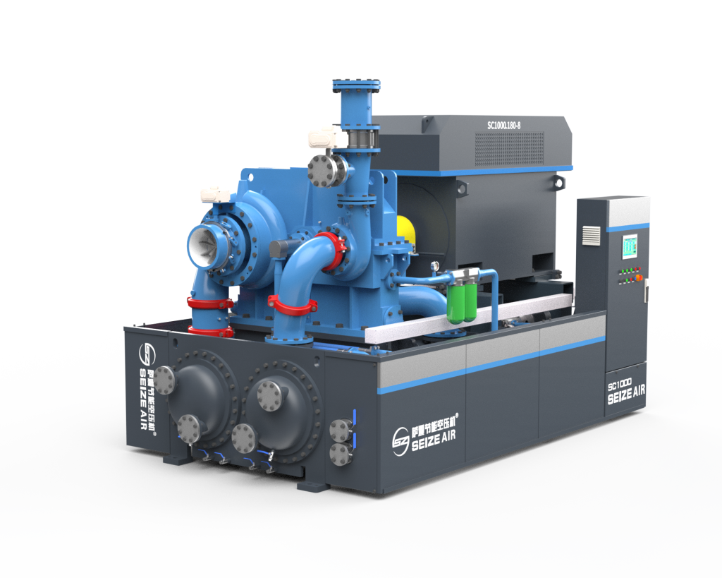
SEIZEAIR industrial centrifugal air compressor with integrated piping, pump assemblies, and electrical control cabinet
1. Why Centrifugal? The Physics of High-Volume Compression
Every compressor type occupies a distinct region on the flow-versus-pressure map. Reciprocating machines excel at high pressure but low flow. Screw compressors dominate the mid-range. Centrifugal compressors own the upper-right quadrant: high flow (typically 100 to over 20,000 m³/h) with discharge pressures reaching 10 to 40 bar(g) in standard configurations, and several hundred bar in specialized multi-casing designs.
The underlying principle is dynamic compression. Unlike positive-displacement machines that trap a fixed volume of gas and mechanically reduce its volume, a centrifugal compressor imparts kinetic energy to the gas by accelerating it through a high-speed impeller, then converts that kinetic energy into static pressure in a stationary diffuser. This is fundamentally a continuous-flow process — there are no valves, no reciprocating masses, and virtually no pulsation.
The advantages for process industries are substantial:
- Oil-free air: No lubricant enters the compression chamber. For ASUs feeding cryogenic distillation columns, this is non-negotiable — even trace oil can freeze and block heat exchangers.
- High reliability and low vibration: With only one major rotating assembly (the pinion shaft with mounted impellers), the mechanical simplicity translates to 3–5 year uninterrupted run times between major overhauls.
- Compact footprint per unit flow: A single centrifugal compressor package can replace a battery of screw machines, saving plot space and simplifying installation, piping, and maintenance logistics.
- Stable discharge pressure: The centrifugal characteristic curve provides inherent pressure regulation — as downstream demand fluctuates, discharge pressure remains within a narrow band even before active controls engage.
These fundamentals explain why SEIZE AIR’s centrifugal compressor solutions are found in steel mills, petrochemical complexes, and LNG plants: the technology matches the scale and reliability requirements of continuous process operations.
2. Impeller Aerodynamics: Where Efficiency Begins
The impeller is the heart of a centrifugal compressor. All the energy that eventually becomes compressed air enters the system at the impeller eye. The quality of that energy transfer — how much of the shaft power becomes useful pressure rise versus waste heat — is determined primarily by aerodynamic design.
2.1 Blade Geometry and the Velocity Triangle
At the impeller inlet, air enters at an absolute velocity determined by the suction pipe diameter and upstream conditions. The impeller rotates at a peripheral speed that can exceed 300 m/s in high-performance stages. The vector difference between these two velocities defines the relative velocity of the gas as it meets the rotating blade — this is the velocity triangle, and getting it right across the entire operating range is the central challenge of impeller design.
Three geometric parameters dominate:
- Blade inlet angle (β₁): Too steep, and the gas separates from the suction side of the blade, causing stall. Too shallow, and the inlet Mach number rises, inducing shock losses. Modern designs use computational fluid dynamics (CFD) to optimize β₁ for the design flow coefficient while maintaining acceptable incidence at off-design conditions.
- Blade exit angle (β₂): This determines the theoretical head (energy per unit mass) added by the stage. Backward-curved blades (β₂ < 90°) are standard for industrial air compressors because they provide a stable, positively-sloped characteristic curve — meaning pressure rises as flow decreases, which is essential for surge avoidance.
- Blade count and splitter configuration: Full-length blades alternating with shorter splitter blades reduce blockage at the inducer (where flow area is most constrained) while maintaining adequate work input. Typical configurations use 8–10 full blades with equal numbers of splitters.
2.2 Mach Number Constraints
As impeller tip speeds increase to achieve higher stage pressure ratios, the relative Mach number at the inducer tip approaches unity. Once the flow goes transonic, shock waves form on the blade suction surface, causing boundary layer separation and a sharp drop in efficiency.
For industrial air compressors operating with atmospheric inlet conditions, tip speeds are typically limited to approximately 280–320 m/s, yielding stage pressure ratios of 1.5–2.5 per stage, depending on working fluid properties. For nitrogen service in ASUs, the higher ratio of specific heats (k ≈ 1.40 for N₂ vs. 1.40 for air) and different gas constant shift the operating envelope slightly.
SEIZE AIR’s engineering approach to Mach number management involves selecting impeller diameters and rotational speeds that keep the inducer relative Mach number below critical thresholds across the full operating map, while using multi-stage configurations to achieve the overall pressure ratio.
3. Multi-Stage Architecture: The Integrally Geared Compressor
A single centrifugal stage can only deliver a limited pressure ratio. To reach the 7–15 bar(g) discharge pressures common in process air systems, multiple stages must be arranged in series. The dominant architecture for industrial air compression is the integrally geared centrifugal compressor.
3.1 How Integrally Geared Designs Work
An integrally geared compressor uses a central bull gear driven by the main motor. Arranged radially around this bull gear are multiple pinion shafts, each carrying one or two impellers. Each pinion runs at its own optimal speed, determined by the gear ratio. This is a critical advantage: the first stage, handling cool, dense inlet air, can run at a lower tip speed, while subsequent stages handling hotter, less dense air can run at progressively higher rotational speeds to maintain optimal specific speed and Mach number.
A typical three-stage configuration for a 10 bar(g) process air compressor might look like:
| Stage | Pinion Speed | Impeller Type | Pressure Ratio | Discharge Temp (before intercooler) |
|---|---|---|---|---|
| 1st | ~18,000 rpm | Semi-open, high-flow | ~2.0 | ~180°C |
| 2nd | ~25,000 rpm | Closed, medium-flow | ~2.0 | ~185°C |
| 3rd | ~32,000 rpm | Closed, low-flow | ~2.2 | ~200°C |
Between each stage, an intercooler reduces the gas temperature to within 10–15°C of ambient. This serves two purposes: it reduces the power required by the downstream stage (compressing cooler gas requires less work), and it keeps discharge temperatures within material and seal limits.
3.2 The Intercooler’s Critical Role
Intercoolers in integrally geared compressors are typically water-cooled shell-and-tube or plate-fin heat exchangers mounted directly on the compressor skid. Their importance extends beyond simple thermodynamics:
- Condensate management: Cooling air below its dew point causes water vapor to condense. Moisture separators and automatic drains between stages prevent liquid carryover into downstream impellers, which would cause erosion.
- Approach temperature: The difference between cooling water inlet temperature and cooled air outlet temperature. A 5–8°C approach is achievable with well-designed coolers; every degree of approach improvement translates to roughly 0.3–0.5% overall power savings.
- Fouling resistance: In regions with poor cooling water quality (common in Middle Eastern and South Asian industrial sites), intercooler fouling is a leading cause of performance degradation. SEIZE AIR packages for these markets often specify larger heat transfer surface area and accessible tube-side cleaning arrangements.
4. Control Systems: Surge Prevention, IGV Modulation, and Turndown
A centrifugal compressor that cannot be controlled is a liability. The most dangerous operating condition is surge — a violent flow reversal that occurs when the compressor operates at low flow and the discharge pressure exceeds what the impeller can sustain. Surge can destroy bearings, damage seals, and in extreme cases, cause catastrophic impeller failure within seconds.
3.2 The Intercooler’s Critical Role
Intercoolers in integrally geared compressors are typically water-cooled shell-and-tube or plate-fin heat exchangers mounted directly on the compressor skid. Their importance extends beyond simple thermodynamics:
- Condensate management: Cooling air below its dew point causes water vapor to condense. Moisture separators and automatic drains between stages prevent liquid carryover into downstream impellers, which would cause erosion.
- Approach temperature: The difference between cooling water inlet temperature and cooled air outlet temperature. A 5–8°C approach is achievable with well-designed coolers; every degree of approach improvement translates to roughly 0.3–0.5% overall power savings.
- Fouling resistance: In regions with poor cooling water quality (common in Middle Eastern and South Asian industrial sites), intercooler fouling is a leading cause of performance degradation. SEIZE AIR packages for these markets often specify larger heat transfer surface area and accessible tube-side cleaning arrangements.
4. Control Systems: Surge Prevention, IGV Modulation, and Turndown
A centrifugal compressor that cannot be controlled is a liability. The most dangerous operating condition is surge — a violent flow reversal that occurs when the compressor operates at low flow and the discharge pressure exceeds what the impeller can sustain. Surge can destroy bearings, damage seals, and in extreme cases, cause catastrophic impeller failure within seconds.
The theoretical minimum work for compression is the isothermal process — compressing at constant temperature. Real compressors with intercooling approach this ideal. Isothermal efficiency is defined as:
η_iso = (Isothermal compression power) / (Actual shaft power)
Well-designed integrally geared centrifugal compressors achieve isothermal efficiencies of 72–78% at design conditions, depending on the number of stages, intercooler effectiveness, and impeller aerodynamics.
7.2 Specific Power and ISO 1217
For apples-to-apples comparison, specific power (kW per m³/min of free air delivered, or kW/100 cfm) measured per ISO 1217 is the standard metric. Typical values for 7–10 bar(g) centrifugal packages are:
| Configuration | Specific Power (kW/m³/min) | Isothermal Efficiency |
|---|---|---|
| 3-stage, no IGV | 0.095–0.105 | 68–72% |
| 3-stage, with IGV | 0.088–0.098 | 73–77% |
| 4-stage, with IGV | 0.085–0.093 | 75–79% |
These numbers assume standard inlet conditions (20°C, 1 bar(a), 0% relative humidity). At site conditions of 45°C and 950 mbar (typical for a Middle Eastern installation at 500 m elevation), the mass flow — and thus power — must be recalculated. A compressor sized for ISO conditions will deliver 8–12% less mass flow at hot-and-high conditions, or consume proportionally more power to deliver the same mass flow.
8. The SEIZE AIR Approach: Modular Engineering for Global Markets
SEIZE AIR has positioned its centrifugal compressor product line to serve customers who need industrial-grade reliability and performance with short delivery times and competitive total cost of ownership. Several engineering choices reflect this philosophy:
Standardized modular packages: Rather than custom-engineering every component, SEIZE AIR uses pre-engineered skid modules that can be configured for different flow, pressure, and utility specifications. This reduces engineering lead time and allows for faster factory acceptance testing.
Oversized intercoolers for tropical markets: For installations in Southeast Asia, South Asia, and the Middle East, where cooling water temperatures of 32–35°C are common, the standard intercooler specification includes additional surface area to maintain approach temperatures without excessive cooling water flow.
Integrated control systems: Rather than relying on third-party PLC integration, SEIZE AIR packages include a factory-configured control system with pre-tuned anti-surge logic, sequenced start-up permissives, and Modbus/Ethernet IP communication for DCS integration.
Local service support: For customers in markets without easy access to OEM field service engineers, SEIZE AIR provides detailed maintenance manuals, on-site training during commissioning, and remote diagnostic support.
9. Looking Ahead: Trends Shaping Centrifugal Compression
The centrifugal compressor is a mature technology, but several trends are pushing the boundaries:
Magnetic bearings: Oil-free magnetic bearing systems eliminate the lube oil system entirely — no pumps, filters, coolers, or oil changes. While primarily seen in high-speed turbo blowers and smaller centrifugal machines today, the technology is migrating upward in power.
Additive-manufactured impellers: 3D-printed impellers with internal cooling channels and optimized blade shapes that cannot be machined are in the prototype stage. The challenge is material properties — additive-manufactured alloys have different fatigue behavior than wrought materials, and certification for pressure-containing rotating parts is still evolving.
Digital twins and predictive maintenance: Real-time performance monitoring with machine learning algorithms that detect incipient problems — bearing degradation, fouling, seal leakage — before they become failures. This is already in deployment at major oil and gas operators and is filtering down to the broader industrial market.
Hydrogen compression: As green hydrogen production scales up, the need for large-flow, oil-free hydrogen compressors is growing. Centrifugal compressors, with their oil-free design and high-flow capability, are well-suited for the electrolyzer outlet and pipeline injection stages of hydrogen infrastructure.
Conclusion
The centrifugal air compressor remains the backbone of compressed air supply for heavy process industries. Its fundamental advantages — oil-free delivery, continuous flow, high reliability, and compact footprint per unit output — have not been surpassed by any competing technology for the high-flow applications that define petrochemical, steel, ASU, and LNG operations.
What has changed is the depth of engineering available at competitive price points. Advances in CFD-driven impeller design, 5-axis CNC manufacturing, integrated digital controls, and modular packaging have democratized access to high-efficiency centrifugal compression. Companies like SEIZE AIR, with a focus on standardized, well-engineered, application-adapted packages, are making it possible for operators in emerging industrial markets to access compression technology that was once the exclusive domain of a handful of global OEMs.
Understanding the technology — from the aerodynamics inside the impeller to the logic of the anti-surge controller — empowers plant engineers and procurement managers to make informed decisions about specifications, suppliers, and lifecycle economics. In an industry where energy cost dominates total cost of ownership, that understanding delivers real financial returns.