
When an oil refinery requires 50,000 cubic meters of compressed air per hour to drive its catalytic cracking units, or a steel mill demands uninterrupted instrument air across a 3-kilometer production line, the choice of compressor technology is not a matter of preference — it is a matter of engineering inevitability. In these scenarios, the centrifugal air compressor stands alone as the only viable solution, combining volumetric scale, energy efficiency, and operational reliability in a way that no other compressor type can match.
This article provides a comprehensive technical deep dive into centrifugal air compression technology — from first principles of fluid dynamics to real-world deployment in heavy process industries. Whether you are a plant engineer evaluating capital equipment, a maintenance manager seeking to understand operational fundamentals, or a procurement professional building technical specifications, this guide covers the core engineering disciplines that make centrifugal compressors the backbone of large-scale industrial air systems.
1. The Fundamental Physics: How Centrifugal Compression Works
At its heart, a centrifugal compressor converts mechanical energy into fluid pressure through two sequential physical processes: acceleration and diffusion.
1.1 From Rotation to Pressure: The Two-Stage Energy Conversion
The compression cycle begins when ambient air enters the compressor inlet and encounters a rapidly rotating impeller. The impeller — spinning at speeds typically between 10,000 and 60,000 RPM, depending on machine size — imparts kinetic energy to the air mass. As air molecules are flung outward by centrifugal force along the impeller’s curved blades, their velocity increases dramatically. At the impeller tip, the air can reach velocities exceeding Mach 0.8 in high-performance designs.
This high-velocity, low-pressure air then enters a stationary component called the diffuser. The diffuser is geometrically designed as a gradually expanding passage. As the air flows through this widening channel, the principle of conservation of mass dictates that velocity must decrease while static pressure rises — this is the Bernoulli principle in action. Approximately 50–70% of the total pressure rise in a centrifugal compressor stage occurs in the diffuser, making its aerodynamic design arguably the most critical element of stage performance.
The final component in the stage is the volute (or scroll casing), which collects the diffused air and further converts residual velocity into pressure while channeling the flow toward either the discharge port or the next compression stage.
1.2 The Euler Turbomachinery Equation: Quantifying Stage Work
The theoretical work input to a centrifugal compressor stage is governed by the Euler turbomachinery equation:
W = u₂ × Cθ₂ − u₁ × Cθ₁Where:
- u₁, u₂ = blade tangential velocity at impeller inlet and outlet
- Cθ₁, Cθ₂ = tangential component of absolute air velocity at inlet and outlet
In most industrial centrifugal compressors, air enters the impeller with minimal pre-swirl (Cθ₁ ≈ 0), simplifying the equation to W ≈ u₂ × Cθ₂. This reveals a fundamental design insight: the work input — and thus the pressure ratio achievable per stage — is directly proportional to the impeller tip speed. This is why high-speed operation is intrinsic to centrifugal compressor design, and why material strength at elevated rotational speeds is a primary engineering constraint.
2.1 Shrouded vs. Unshrouded Impellers
| Characteristic | Shrouded (Closed) | Unshrouded (Open / Semi-Open) |
|---|---|---|
| Efficiency | Higher — no tip leakage | Slightly lower — tip gap losses |
| Structural integrity | Lower tip speed limit | Higher tip speed capability |
| Erosion tolerance | Less tolerant | More tolerant |
| Manufacturing complexity | Higher (brazed or welded shroud) | Lower (5-axis milled from billet) |
| Typical application | Lower-pressure air service | High-pressure, high-speed stages |
For industrial air compression where discharge pressures typically range from 2 to 15 bar(g), shrouded impellers dominate the first and second stages due to their superior aerodynamic efficiency. The shroud eliminates the clearance gap between blade tips and the stationary housing, preventing the high-pressure air from recirculating back to the low-pressure side of the blade passage. This tip leakage flow, when present in unshrouded designs, not only reduces efficiency but also generates secondary flow vortices that narrow the stable operating range.
2.2 Backward-Curved Blades: The Industry Standard
Virtually all modern industrial centrifugal compressors use backward-curved impeller blades (also called backswept blades). The blade exit angle is oriented opposite to the direction of rotation, typically between 30° and 55° from the radial direction. This geometry offers three critical advantages:
- Stable operating range (wider surge margin): The head-versus-flow characteristic curve of backward-curved blades has a continuously negative slope, meaning that as flow decreases, the developed head increases — but at a predictable, controllable rate. This contrasts with forward-curved blades, where the curve can exhibit a flat or even positively sloped region that makes the compressor susceptible to unstable operation.
- Higher efficiency at design point: Backward-curved blades produce less absolute velocity at the impeller exit for a given tip speed, which means the diffuser receives air at a lower Mach number. Lower diffuser inlet velocities translate to lower friction losses in the diffuser passage, directly improving stage efficiency.
- Lower power consumption at overload: When operating at higher-than-design flow rates, backward-curved impellers exhibit a self-limiting power characteristic. The power curve flattens at high flow, preventing motor overload — a critical safety feature in industrial applications where process demand can fluctuate.
2.3 Three-Dimensional Blade Geometry
The evolution from two-dimensional (ruled-surface) blades to three-dimensional (free-form) blades represents one of the most significant advances in centrifugal compressor efficiency over the past two decades. Three-dimensional blades incorporate compound curvature — the blade shape varies not only along the meridional plane but also across the blade span from hub to shroud. Computational Fluid Dynamics (CFD) optimization of 3D blade geometry can recover 2–4 percentage points of stage efficiency compared to conventional 2D designs, primarily by:
- Reducing secondary flow losses at the hub and shroud boundary layers
- Better controlling the blade loading distribution to avoid local flow separation
- Optimizing the leading-edge sweep to accommodate varying incidence angles across the span
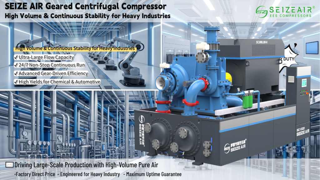
SEIZE AIR Centrifugal Compressor Unit
3. Multi-Stage Compression: Engineering for High Pressure Ratios
A single centrifugal compressor stage can achieve a pressure ratio of approximately 1.5 to 3.5, depending on impeller tip speed and gas properties. For industrial air compression requiring overall pressure ratios of 8 to 15 (discharge pressures of 7 to 14 bar(g) from atmospheric inlet), multiple stages must be arranged in series.
3.1 Stage Stacking: The Numbered Stage Architecture
In a typical three-stage centrifugal air compressor, each stage contributes to the total pressure buildup:
- Stage 1 (Low-Pressure): Compresses air from atmospheric (~1 bar(a)) to approximately 2.0–2.5 bar(a). Uses the largest impeller diameter because volumetric flow is highest at the inlet.
- Stage 2 (Intermediate-Pressure): Receives air at ~2.0 bar(a) and compresses to approximately 4.5–5.5 bar(a). Impeller diameter is reduced to match the lower volumetric flow.
- Stage 3 (High-Pressure): Further compresses to the final discharge pressure of 7–14 bar(a). The smallest impeller, operating at the highest pressure level.
The progressive reduction in impeller diameter across stages is not arbitrary — it follows from the relationship between mass flow rate (constant through the machine in steady state) and volumetric flow rate (decreases as density increases with pressure). Since compressor stage geometry must be matched to the volumetric flow it handles, later stages require narrower flow passages and smaller impellers.
3.2 Intercooling: The Thermodynamic Imperative
Between compression stages, the air passes through intercoolers — typically shell-and-tube or fin-fan heat exchangers using cooling water or ambient air. Intercooling serves two critical purposes:
Thermodynamic efficiency: Compressing air is most efficient when the air is cold. In an ideal isothermal compression process (constant temperature), the work required is the theoretical minimum. Real compressors operate along a polytropic path that lies between the adiabatic and isothermal limits. Intercooling brings the process closer to the isothermal ideal by removing the heat of compression between stages, reducing the work required in subsequent stages. A well-designed intercooling system can reduce total power consumption by 10–15% compared to an uncooled multi-stage machine at the same overall pressure ratio.
Material protection: Compressor discharge temperatures can reach 200–250°C without intercooling. While this is within the metallurgical limits of most impeller materials, downstream components — seals, bearings, instrumentation, and piping — have lower temperature tolerances. Intercooling maintains stage inlet temperatures at manageable levels, typically 35–50°C above cooling water temperature.
3.3 The Bull Gear and Pinion Arrangement
Multi-stage industrial centrifugal compressors commonly use an integrally geared configuration. A large-diameter bull gear, driven by the main motor, meshes with multiple smaller pinion gears — one per compression stage. Each pinion shaft carries an impeller at one or both ends. This arrangement provides two engineering advantages:
- Each stage can operate at its own optimal speed, improving overall efficiency
- The intercooler can be positioned directly between stages without complex external piping
The alternative is the single-shaft (inline) configuration, where all impellers are mounted on a common shaft rotating at a single speed. While mechanically simpler, the single-shaft design forces a compromise on stage-specific optimal speeds. Integrally geared machines dominate the 500–5,000 kW range typical of industrial air compression.
5.1 Electric Motor Drives
The vast majority of industrial centrifugal air compressors are driven by electric motors, typically three-phase induction motors or synchronous motors in the 500 kW to 10 MW range. For integrally geared compressors, the motor operates at its synchronous speed (commonly 1,500 or 1,800 RPM for 50 Hz and 60 Hz grids, respectively), while the gear set provides the speed multiplication required for the impeller stages.
High-voltage motors (3.3 kV, 6.6 kV, or 10 kV) are standard for machines above approximately 1,500 kW, as they reduce current draw and allow more compact cable sizing. Direct-on-line (DOL) starting is common up to several megawatts; larger machines may employ soft starters or variable frequency drives (VFDs) to limit inrush current.
5.2 Variable Speed Operation and Energy Optimization
Centrifugal compressors follow affinity laws that govern the relationship between speed, flow, head, and power:
- Flow is proportional to speed: Q₂ / Q₁ = N₂ / N₁
- Head is proportional to speed squared: H₂ / H₁ = (N₂ / N₁)²
- Power is proportional to speed cubed: P₂ / P₁ = (N₂ / N₁)³
The cubic relationship between speed and power is the foundation of centrifugal compressor energy optimization. When a process requires less air, reducing the compressor speed by 10% reduces power consumption by approximately 27%. This is dramatically more efficient than inlet throttling or discharge bypass, which waste the energy already invested in compression.
Variable frequency drives (VFDs) enable this speed modulation. Combined with inlet guide vanes (IGVs) that pre-swirl the incoming air to adjust the stage characteristic, a VFD-equipped centrifugal compressor can maintain high efficiency across a turndown range of 50–100% of design flow. For processes with fluctuating air demand — which describes virtually all industrial plants — the energy savings from VFDs typically recover their capital cost within 2–4 years.
5.3 Steam Turbine and Gas Turbine Drives
In petrochemical plants and refineries where steam is abundantly available from process boilers or waste heat recovery, steam turbine drives offer an alternative to electric motors. Steam turbines provide inherent variable speed capability without the cost of VFD electronics, and they decouple the compressor from electrical grid reliability concerns. Condensing steam turbines driving centrifugal compressors are common in air separation units (ASUs) and large refinery instrument air systems.
Gas turbine drives, while less common for pure air compression service, are used in remote locations without reliable grid power — particularly in upstream oil and gas applications and LNG liquefaction plants where the gas turbine can run on process gas.
6. Control Systems: Anti-Surge Protection and Capacity Regulation
6.1 The Surge Phenomenon: Understanding the Operational Limit
Surge is the most destructive operational hazard facing any centrifugal compressor. It occurs when the flow through the compressor drops below a critical minimum, causing the impeller to lose its ability to maintain forward flow. The compressed gas in the downstream piping momentarily reverses direction, rushing backward through the compressor. The impeller recovers, re-establishes forward flow, and the cycle repeats — typically at frequencies of 0.5 to 5 Hz.
This flow oscillation generates enormous mechanical loads: axial thrust reversals that hammer the thrust bearing, temperature spikes in the gas path, and vibration amplitudes that can exceed safe limits within seconds. Unchecked surge can destroy a compressor in minutes.
6.2 Anti-Surge Control Architecture
Modern anti-surge control systems employ a multi-layered defense:
Surge line mapping: During commissioning, the actual surge point is experimentally determined at multiple operating speeds, typically by carefully approaching surge while monitoring high-frequency pressure and vibration signals. This data defines the surge line on the compressor performance map.
Surge control line: A safety margin (typically 8–15% of design flow) is added to create the surge control line. When the operating point approaches this line, the anti-surge controller begins opening the blow-off or recycle valve.
Blow-off / recycle valve: This valve opens to vent compressed air to atmosphere (blow-off) or recirculate it to the compressor inlet (recycle). Recycle is more energy-efficient because the compression work invested in the air is partially recovered, but it requires an aftercooler in the recycle loop to prevent inlet temperature from rising.
Rate-of-change detection: Advanced controllers monitor not just the proximity of the operating point to the surge line but also the rate at which it is approaching. A rapid flow reduction (e.g., from a sudden downstream valve closure) triggers preemptive valve opening before the operating point reaches the surge control line.
6.3 Capacity Control Strategies
Three primary methods regulate centrifugal compressor output to match demand:
| Method | Turndown Range | Part-Load Efficiency | Response Speed |
|---|---|---|---|
| Inlet Guide Vanes (IGV) | ~70–100% | Good | Fast (< 1 sec) |
| Variable Speed (VFD) | ~50–100% | Excellent | Moderate (motor ramp rate) |
| Inlet Throttling | ~80–100% | Poor | Fast |
Combined IGV + VFD control achieves the widest efficient operating range and is the preferred configuration for modern large centrifugal air compressors in process service.
8. Industrial Applications: Where Centrifugal Technology Proves Its Value
8.1 Air Separation Units (ASUs)
Air separation is arguably the most demanding application for compressed air. An ASU compresses atmospheric air to 5–10 bar(g), purifies it to remove CO₂ and moisture, then cools it to cryogenic temperatures (−180°C to −195°C) to separate oxygen, nitrogen, and argon by fractional distillation. The compressor must deliver:
- 100% oil-free air: Hydrocarbon contamination at ppm levels can form explosive residues in the heat exchangers and distillation columns. Centrifugal compressors deliver inherently oil-free compression.
- Stable flow: Fluctuations in air supply disturb the thermal balance of the cold box, affecting product purity. The flat operating characteristic of a well-designed centrifugal compressor at its design point supports the precision control that ASU operation requires.
- High volume: Modern ASUs producing 2,000–5,000 tonnes per day of oxygen require 100,000–300,000 Nm³/h of air. Only centrifugal compressors can deliver at this scale in a single train.
Explore SEIZE AIR solutions for air separation and large-scale process industries.
8.2 Petrochemical and Refinery Service
In refineries, instrument air and process air represent safety-critical utilities. A loss of instrument air can cause control valves to fail in position or — depending on fail-safe configuration — close or open, potentially triggering a unit shutdown. Refinery air compressors are typically specified for 99.5%+ availability, a target that centrifugal compressors routinely achieve with properly scheduled maintenance.
The refinery environment also imposes specific design requirements: motors and instrumentation must be certified for hazardous area classification (typically Zone 2, Group IIB+H₂), and the compressor package must include provisions for corrosive atmosphere protection in coastal or sour-service locations.
8.3 Steel Manufacturing
Integrated steel mills consume compressed air across the entire production chain: blast furnace instrumentation, BOF (Basic Oxygen Furnace) oxygen lance cooling, continuous casting machine pneumatics, and finishing line actuation. The sheer physical scale of a steel plant — often 2 to 5 square kilometers — means that compressed air distribution networks are extensive, with significant pressure drop between the compressor house and distant consumers. Centrifugal compressors, with their high discharge pressure capability relative to blowers or low-pressure screw machines, can overcome these distribution losses while maintaining economical specific power.
8.4 LNG and Cryogenic Processing
LNG liquefaction trains compress natural gas refrigerant streams to 40–60 bar(g), well above the typical industrial air range. However, the utility air and nitrogen systems that support LNG plants — instrument air, seal gas, purge air — operate in the 7–15 bar(g) range where centrifugal air compressors are the standard choice. The critical requirement in LNG service is reliability over multi-year continuous runs between scheduled turnarounds; unplanned compressor downtime can curtail LNG production with revenue impacts measured in millions of dollars per day.
9. Future Trends: Digitalization and Efficiency Frontiers
9.1 Aerodynamic Optimization Through CFD and AI
Computational Fluid Dynamics has been integral to compressor design since the 1990s, but the frontier is shifting from steady-state Reynolds-Averaged Navier-Stokes (RANS) simulations to unsteady Large Eddy Simulation (LES) and, increasingly, to AI-assisted multi-objective optimization. Modern design workflows can evaluate thousands of impeller geometry variants against efficiency, operating range, and mechanical stress objectives simultaneously, converging on Pareto-optimal designs that no human engineer would intuitively arrive at.
9.2 Digital Twin and Predictive Maintenance
Leading compressor manufacturers are deploying digital twin technology — real-time computational models of individual compressor installations that receive operating data from the plant’s DCS or SCADA system. The digital twin continuously compares actual performance against the baseline performance map, detecting degradation trends (fouling, seal wear, bearing clearance changes) weeks or months before they would trigger alarm thresholds. This enables condition-based maintenance scheduling that avoids both premature overhauls (wasting service life) and reactive repairs (risking unplanned downtime).
9.3 Magnetic Bearings and Oil-Free Lubrication
Active magnetic bearings (AMBs) eliminate the oil lubrication system entirely — no lube oil pumps, coolers, filters, or reservoirs. The rotor is levitated in a magnetic field, with position sensors and control electronics maintaining the shaft position within micron-level tolerances. AMB-equipped centrifugal compressors are already deployed in specialized applications (subsea gas compression, high-purity processes) and are expected to migrate into mainstream industrial air service as costs decline. The combination of magnetic bearings with high-speed permanent magnet motors — eliminating the gearbox altogether — represents the ultimate simplification of the centrifugal compressor drivetrain.
Conclusion
The centrifugal air compressor is a mature technology that continues to evolve at its performance frontiers. Its fundamental operating physics — converting rotational kinetic energy into fluid pressure through aerodynamic acceleration and controlled diffusion — has not changed, but the precision with which that physics is engineered has advanced dramatically. Modern centrifugal compressors are the product of computational fluid dynamics, advanced materials, precision manufacturing, and sophisticated control systems working in concert.
For the heavy process industries that form the backbone of global industrial infrastructure — petrochemicals, steel, air separation, and LNG — the centrifugal compressor remains irreplaceable at the scale, reliability, and efficiency that these industries demand. Understanding the core technology and design principles covered in this article provides the foundation for informed equipment selection, specification development, and operational optimization.